Improving and Confirming Accuracy – Locating with an SR-24LE and SR-20
DANGER
Exposing the utility is the only way to be certain of its location. If excavating a utility, periodically re- check the measured depth and position to avoid damaging the utility and to identify additional utility signals that may have been overlooked.
Factors Affecting Accuracy
The following conditions can affect the accuracy of a locate:
- Distortion due to local interference or poor signal strength. Distortion is caused by the impact of nearby fields, nearby conductors, magnetic flux, or other interference on the circular electromagnetic field. Distortion is detected by comparing the information from the Tracing Line, Proximity Number, Signal Strength, measured depth, Signal Angle readings, and Upper Antenna measurements.
- Bleed over from the presence of other cables or utilities. Bleed over happens when the signal from the transmitter couples onto nearby non-target lines. The SR-24LE can receive the same frequency on multiple non-target lines. Bleed over can distort fields and illuminate unwanted utility lines. If possible, use lower frequencies and eliminate connections between other utilities.
- The presence of tees, turns, or splits in the line. Turns or tees can cause a sudden increase in the Tracing Line Distortion Response. If following a signal that suddenly becomes distorted, circle the last location of a clear signal at a distance of approximately 6 m [20 ft]. Find the line nearby, to determine whether or not the distortion is coming from a local turn or tee in the line.
- Varying soil conditions. Very wet or very dry soil can affect signal coupling. Saturating the soil with very salty water may strengthen the circuit. Very dry soil may weaken the circuit, if grounding is reduced.
- The presence of large, metal objects. The presence of large, metal objects can cause unexpected increases or decreases in Signal Strength. This type of distortion appears stronger at higher frequencies.
- Low signal srength. If the signal is low, attempt to improve the signal as specified in the following section.
Signal Strength
If the Tracing Line cannot be centered or if it moves across the screen erratically, the SR-24LE may not be receiving a clear signal, stable measured depth, or a reliable Proximity Number.
To attempt to improve the signal, do at least one of the following:
- Check the transmitter and make sure that it is well grounded.
- Check the tracing circuit’s signal strength by pointing the lower antenna at one of the transmitter leads. Improve the circuit if a weak signal is shown.
- Check that the SR-24LE and the transmitter are operating on the same frequency.
- Switch to a higher frequency to overcome resistance and to induce more current onto the line.
- Switch to a lower frequency to reduce bleed over.
Clipping
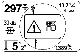
Clipping occurs when the receiver cannot properly process the signal because the Signal Strength is too large. Clipping occurs most often close to powerful sondes and high current power lines. When clipping occurs, the SR-24LE displays a warning symbol on the screen.

The SR‑24LE responds to clipping by attenuating the measurement. Attenuation reduces the intensity of the Signal Strength so the SR‑24LE can measure it. If the SR‑24 is still experiencing clipping, increase the distance between the SR‑24LE and the target line.
No Signal Icon
You can enable the No Signal icon to display when there is no meaningful signal. The No Signal icon gives a fast and easy notification that no signal is detected.
![]()
Note: The No Signal icon is disabled by default. Refer to the Customizing Display Elements section for instructions on how to enable the No Signal icon.
If the No Signal icon appears, try the following to attempt to gain a signal:
- Change the grounding
- Change the frequency
- Use induction
- Move the transmitter
Center Signal Strength
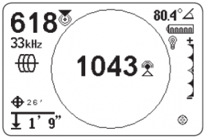
Select the Center Signal Strength option to display the Signal Strength in the center of the screen. The Center Signal Strength option makes the Signal Strength easier to see when locating using Signal Strength alone.

Note: The Center Signal Strength option is disabled by default. Refer to the Customizing Display Elements section for instructions on how to enable the Center Signal Strength option.
Signal Focus Control
Signal Focus Control acts as a magnifying glass on the signal. It narrows the sample bandwidth and displays more stable incoming signals, allowing the SR‑24LE to focus on a particular signal with increased detail.
Note: The selection of a narrow bandwidth increases the detection distance and precision, but slows the refresh rate of the display. As a result, when using the narrowest setting, move the SR‑24LE along the line more slowly.
The Signal Focus Control is disabled by default and must be enabled in the Display Settings screen to make any adjustments to it.
When the Signal Focus Control is activated, from the Active View Area, use the Up and Down Arrow Keys to set it to one of the following bandwidths:
- 4 Hz, wide (default setting when the Signal Focus
Control is disabled) - 2 Hz
- 1 Hz
- 0.5 Hz
- 0.25 Hz, narrow

Note: The Signal Focus Control option is disabled by default. Refer to the Customizing Display Elements section for instructions on how to enable the Signal Focus Control option.
Tracing Circuit
A weak signal can often be improved by changing the tracing circuit. To improve the circuit, perform one or more of the following:
- Wet the soil around the ground stake.
- Move the ground stake away from the target line.
- Use a larger ground, such as a shovel blade.
- Ensure that the target line is not commonly bonded to a utility. If bonded, undo the common bond, only
if it is safe to do so. Reconnect bonds when locate is complete. - Change the frequency.
- Move the transmitter.
- Locate from the other direction along the line.
Confirming Accuracy
To confirm the accuracy of a locate, check that all of the following are true:
- The Guidance Arrows and Guidance Line are aligned with the Tracing Line.
- The Tracing Line shows little or no distortion.
- The Proximity Number and Signal Strength maximize when the Tracing Line crosses the
map center. - The measured depth increases appropriately and the Tracing Line remains aligned when the Depth Verification Test is performed.
Current Measurement (mA) and Signal Angle
The values displayed on the screen for Current Measurement (mA) and Signal Angle are indicators you can use to verify the accuracy of a locate. When the Current Measurement (mA) is displayed and the Guidance Arrows and Tracing Line are aligned, you can be more confident your locate is accurate.
The SR‑24LE detects the Current Measurement (mA) of the target line and displays it in the upper right corner of the screen. The Current Measurement (mA) is only displayed when the SR‑24LE is directly over the target line. When the SR‑24LE is not over the target line, the target line’s Signal Angle displays instead of the Current Measurement (mA).
