CS65x to CS65xr Upgrade Instructions
Read the steps below to convert a RIDGID SeeSnake CS65x unit to a CS65xr.
Table of Contents
Disassembly
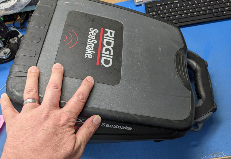
1. Remove the lid.
2. Rear view screw removal.
3. Front view screw removal.
4. Side view(L) screw removal.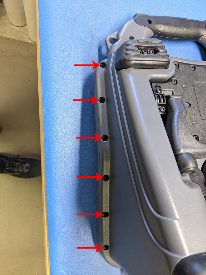
5. Side view(R) screw removal.
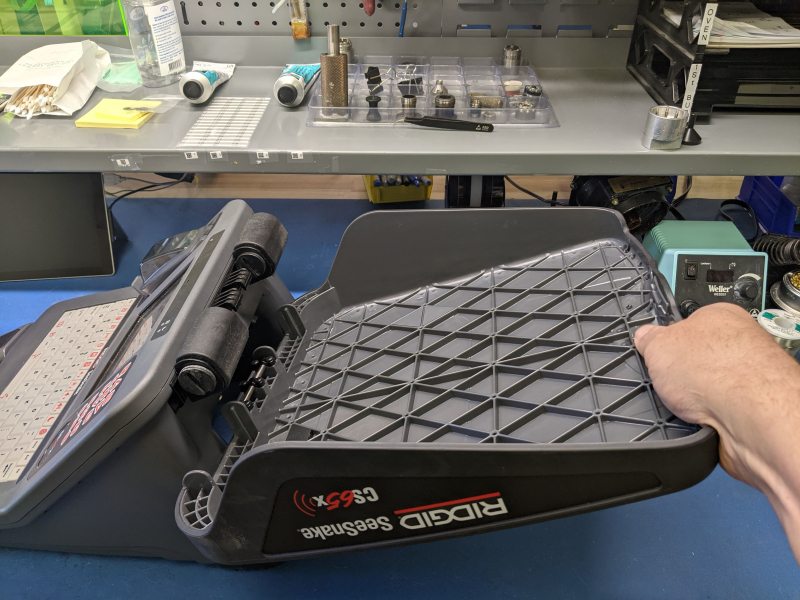
6. Separate the two cases.
7. Unplug the cables for the battery, external power adapter, tracing lug, GPS antenna, and bulkhead connector.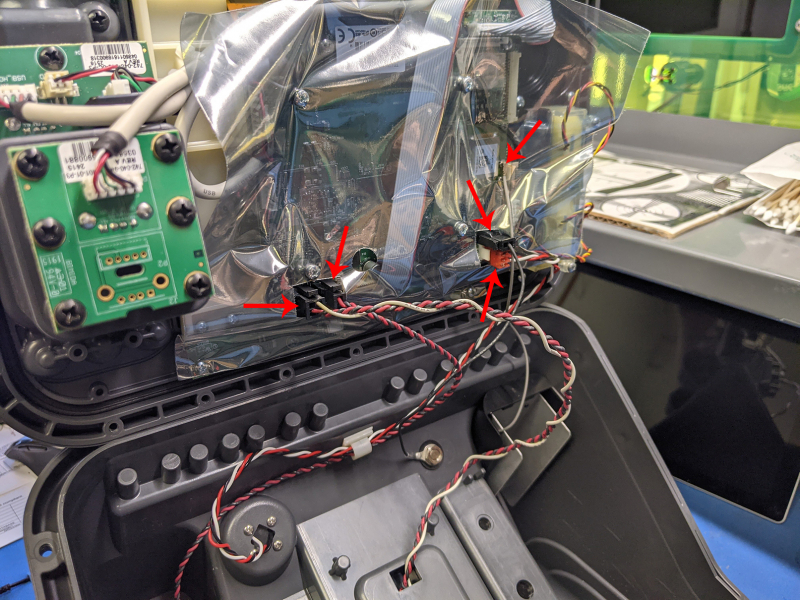
8. Front panel removed from the case.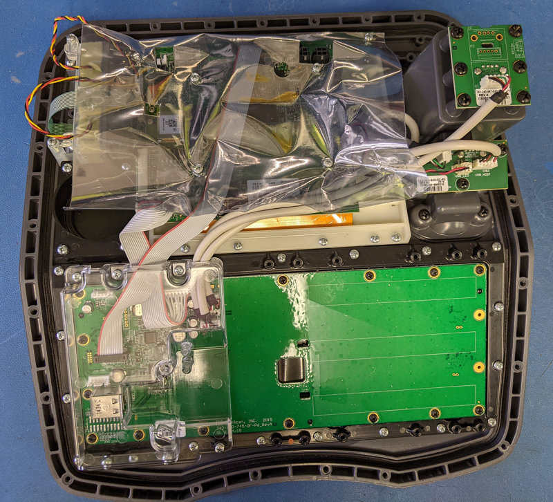
9. Remove the ESD shielding from the circuit board (6 screws).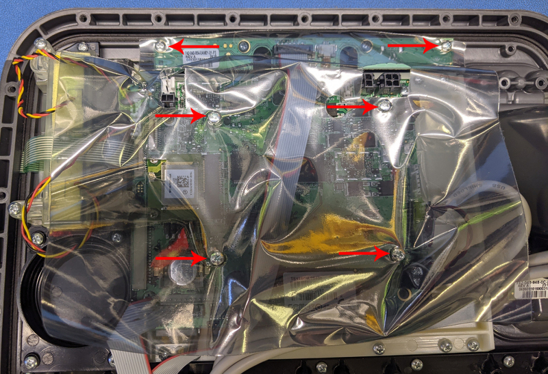
10. Shielding removed.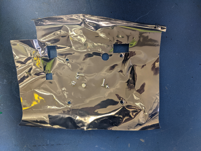
11. Unplug the brow board cable.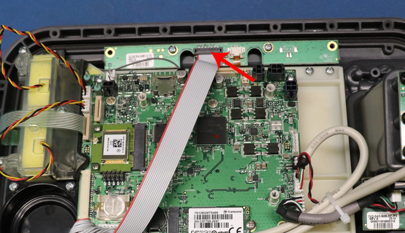
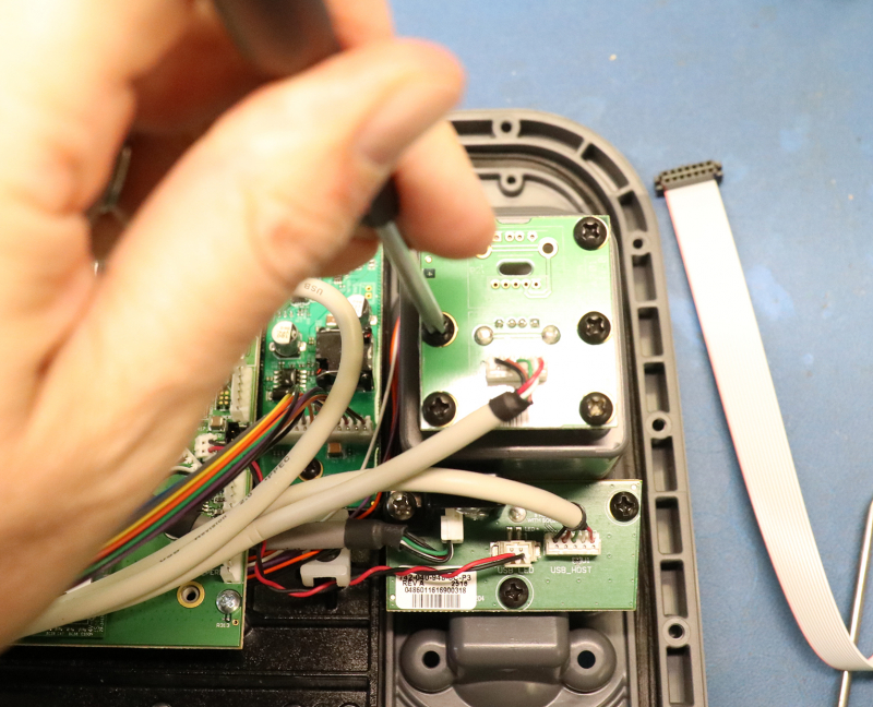
12. Remove the 6 screws securing the top USB board and remove the 3 securing the bottom USB board.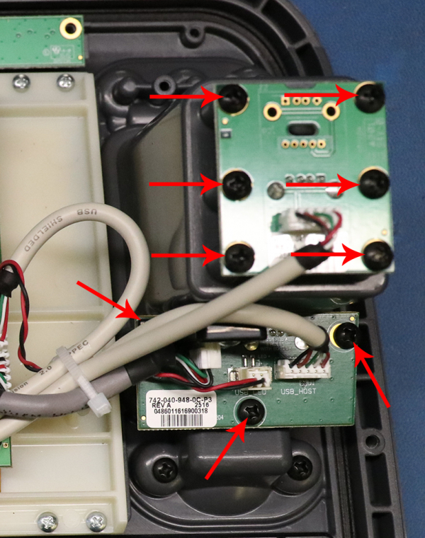
13. Cut the zip tie securing the cables for the USB boards and LED.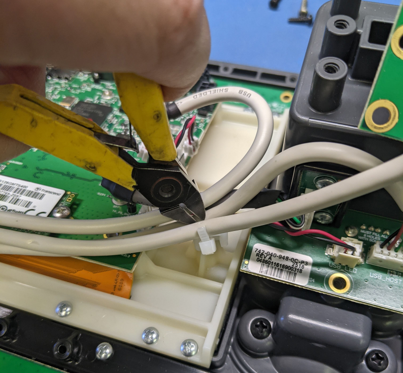
14. Unplug the cables for the USB, the LED and USB board from the iMX6 PCBA, and free the USB boards from the slots on the front panel.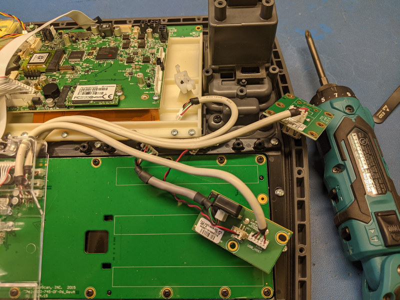
15. Remove the 4 screws securing the mouse hole cover.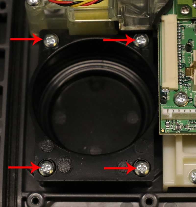
16. Set the mouse hole cover and hardware aside to be re-used.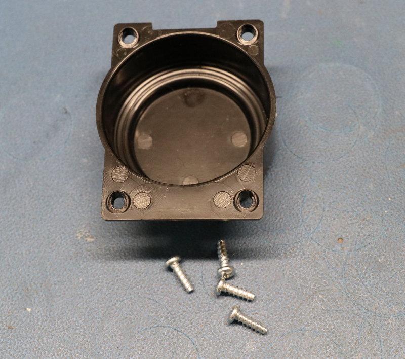
17. Unlatch the keypad ribbon connector, remove the keypad ribbon cable and unplug the two fan cables from the iMX6 PCBA.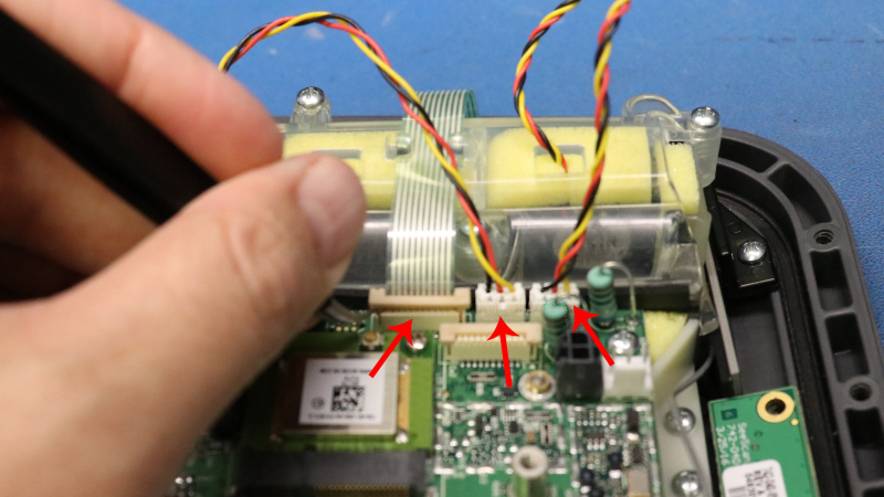
18. Free the keypad ribbon cable from the fan assembly cover and remove the 3 screws securing the fan assembly cover.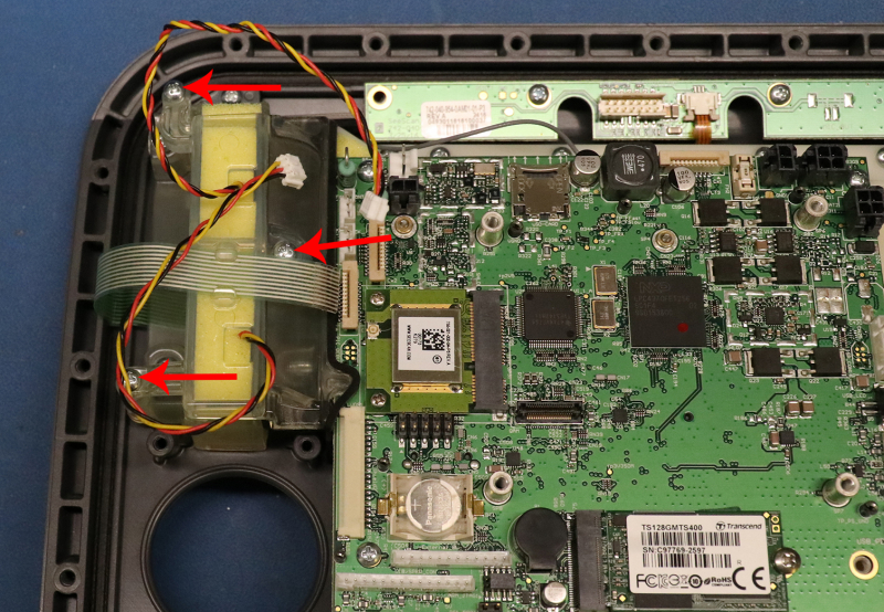
19. Set the cover and hardware aside to be re-used.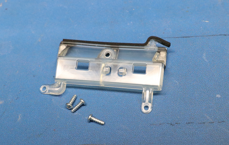
20. Remove the 4 screws securing the fan assembly to the front panel.
21. Set the fan assembly and hardware aside to be re-used.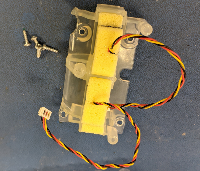
22. Remove the 1 screw securing the Wi-Fi antenna retainer.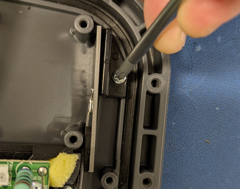
23. Set the retainer and hardware aside to be re-used.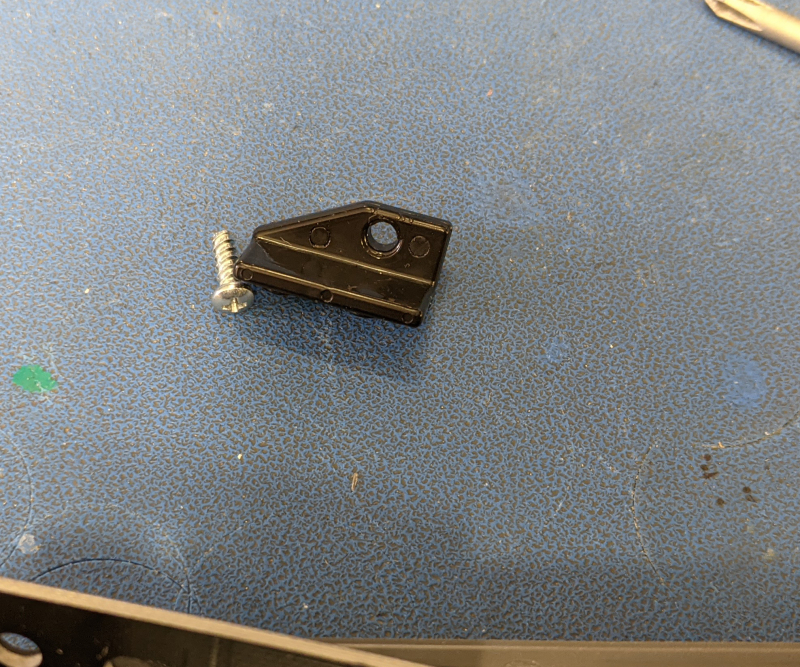
24. Unlatch the ribbon cable connector and unplug the ribbon cable from the brow board.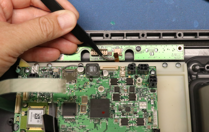
25. Remove the 2 remaining screws securing the brow board.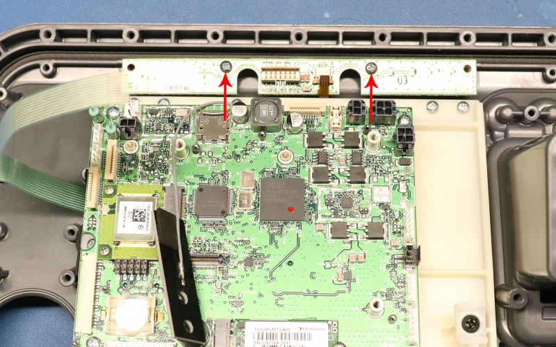
26. Set the brow board and hardware aside to be re-used.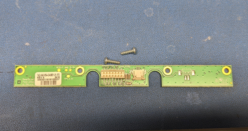
27. Remove the 6 screws securing the cover on the audio/USB board cabling.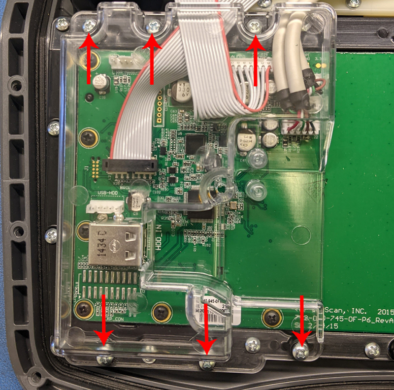
28. Set the cover and hardware aside to be re-used.
29. Remove the 19 screws securing the keyboard assembly to the front panel.
30. Set the keyboard assembly and hardware aside to be re-used.
31. Remove the 2 screws securing the GPS module and remove it.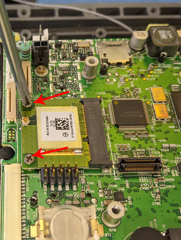
32. Set the GPS and hardware aside to be re-used.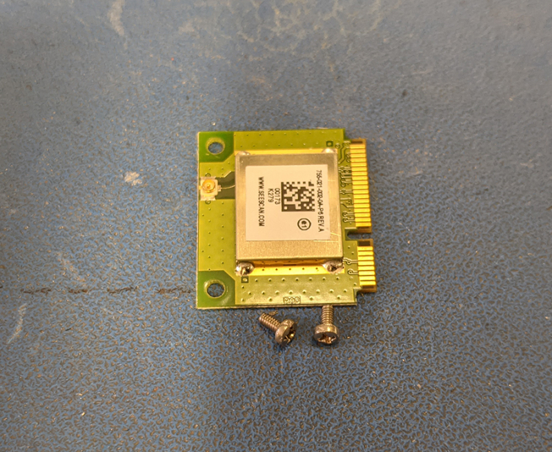
33. Remove the 1 screw securing the SSD and remove it.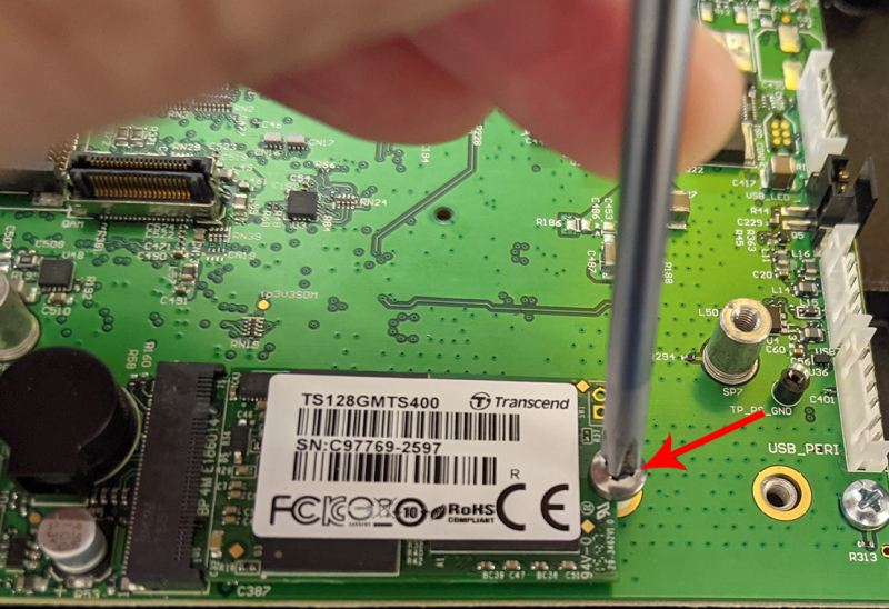
34. Set the SSD and hardware aside to be re-used.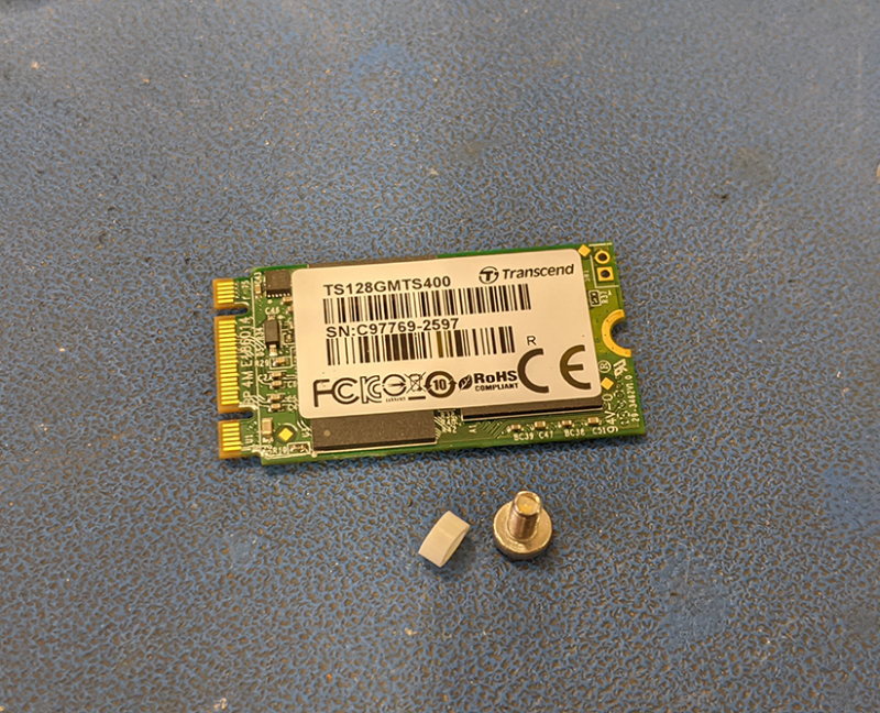
35. Remove the 13 screws securing the LCD/iMX6PCBA to the front panel.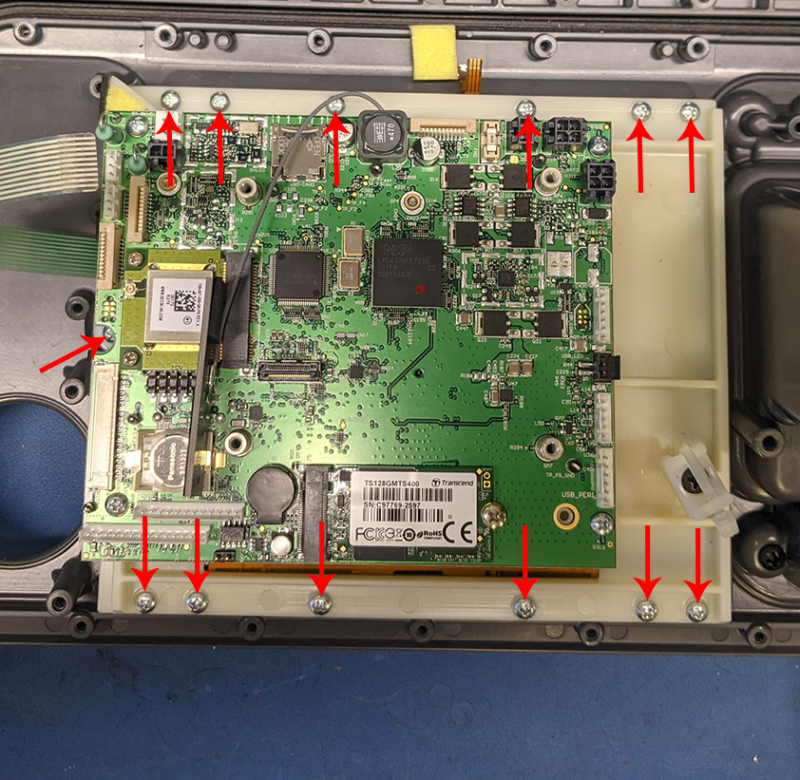
36. Remove the 4 screws securing the iMX6 PCBA to the LCD assy.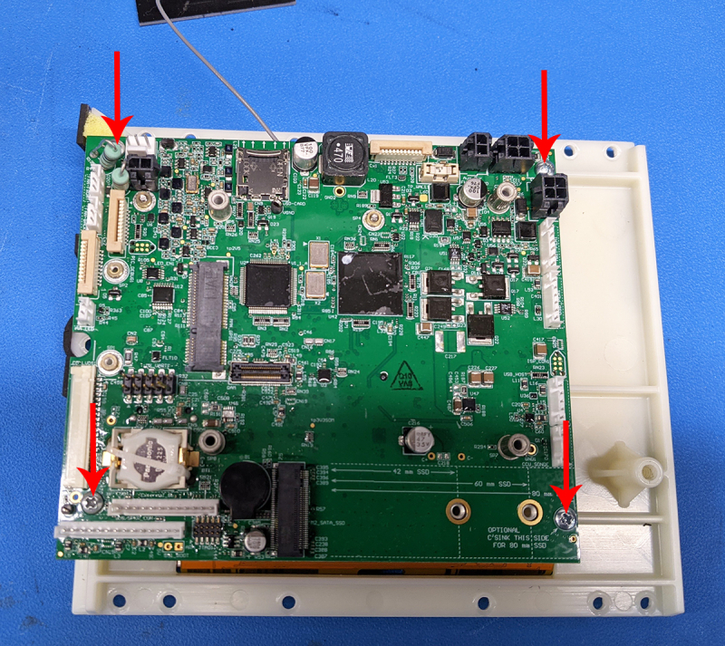
37. Remove the iMX6 PCBA from the LCD assy and set it aside (it will be exchanged for one w/ no S/N programmed into it).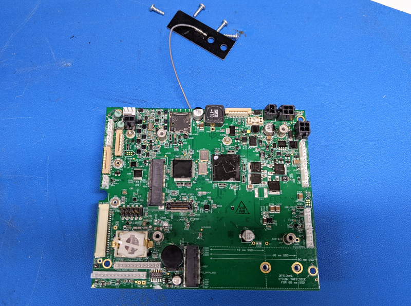
38. Unplug the Wi-Fi antenna from the iMX6 PCBA.
39. Set Wi-Fi antenna aside to be re-used.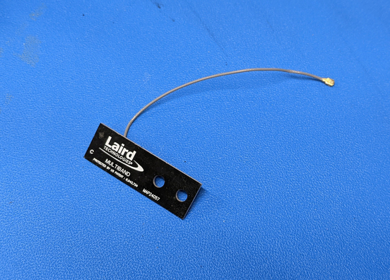
40. Remove the 2 screws securing the LCD interface board and the screw securing the zip tie holder to the LCD frame.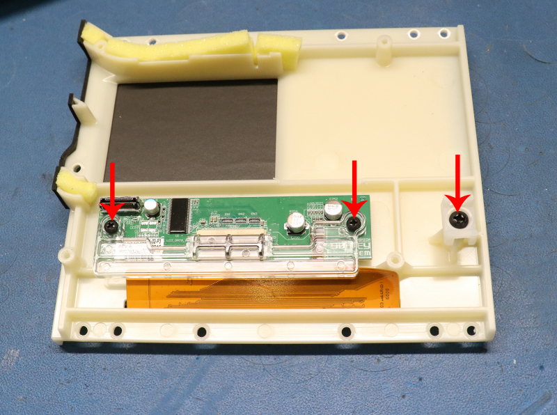
41. Set aside the hardware to be re-used.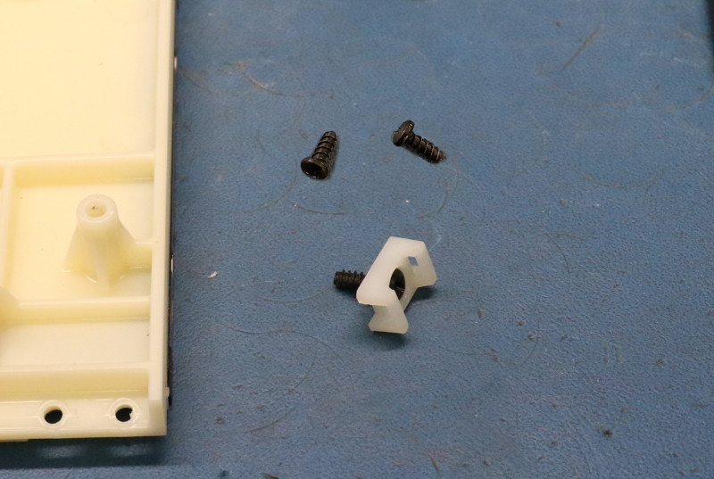
42. Remove the 2 screws securing the USB cover latch to the front panel.
43. Set the latch, the 2 o-rings, and hardware aside to be re-used.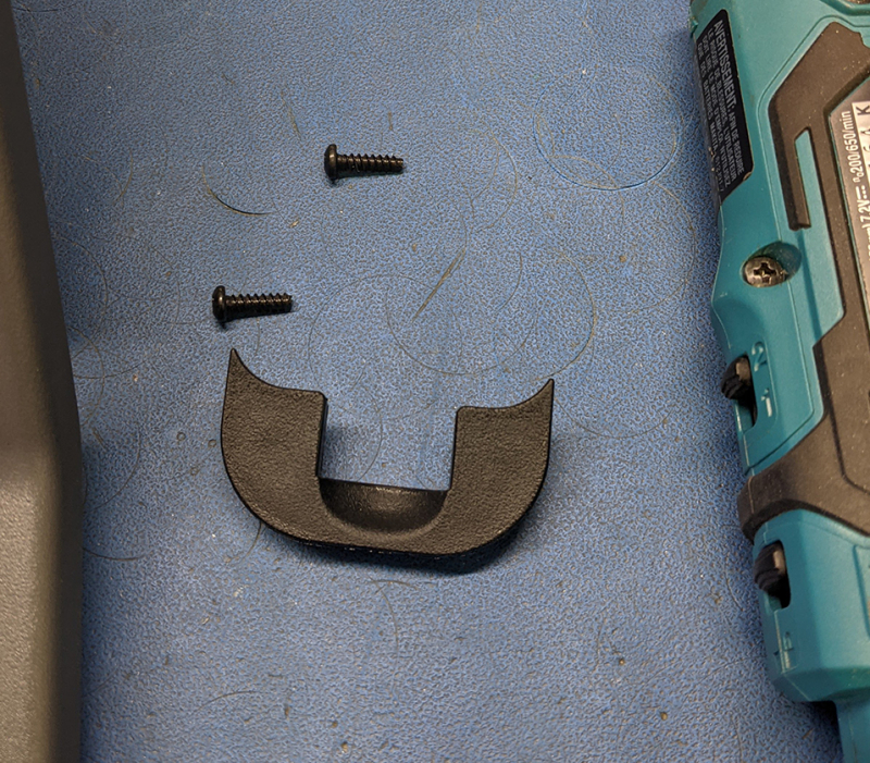
44. Remove the 3 screws securing the USB cover hinge to the front panel.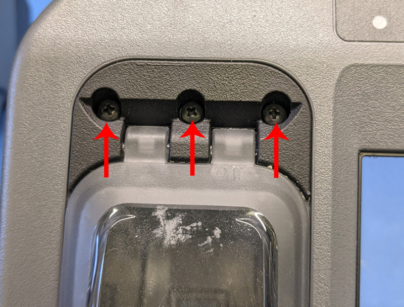
45. Set aside the cover hinge, the USB cover, and hardware aside to be re-used.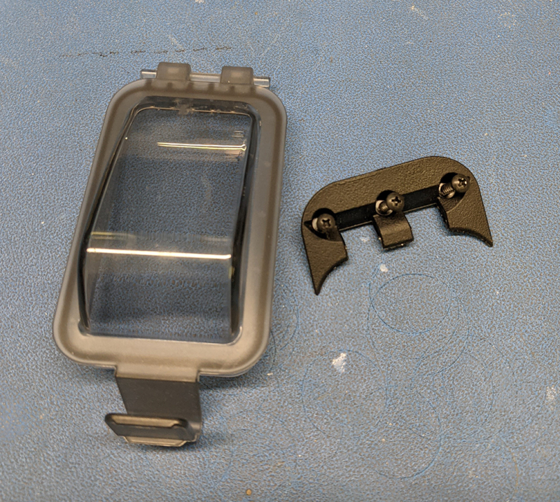
46. Remove the panel gasket and install it on the new one.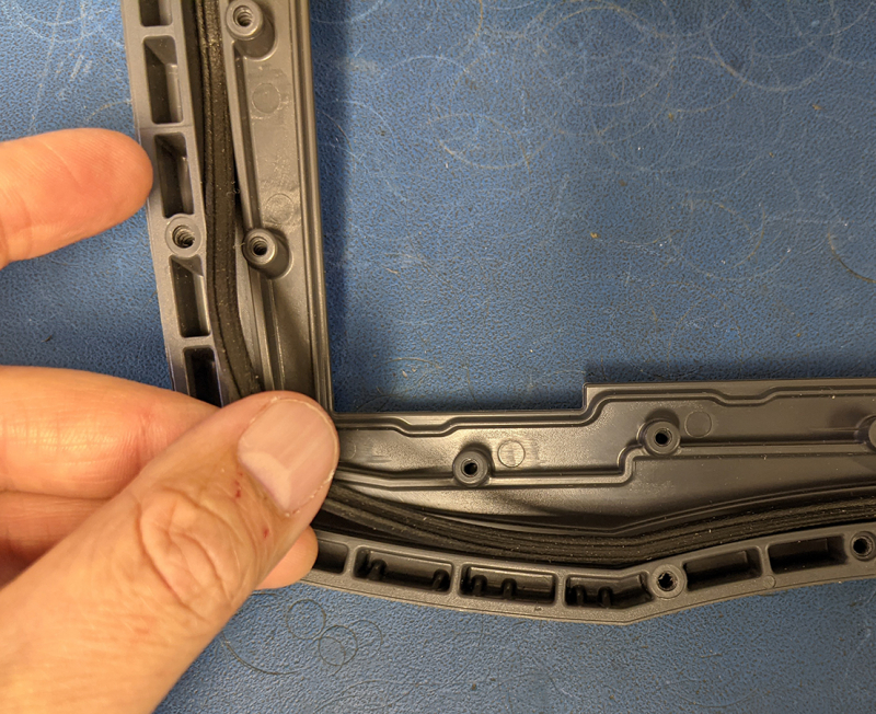
Assembly
47. Install the 2 o-rings in the screw holes for the USB cover latch.
48. Install the latch.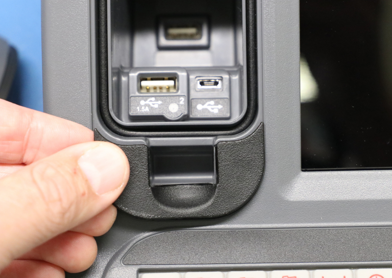
49. Hold the latch in place and thread the 2 screws in place to secure it.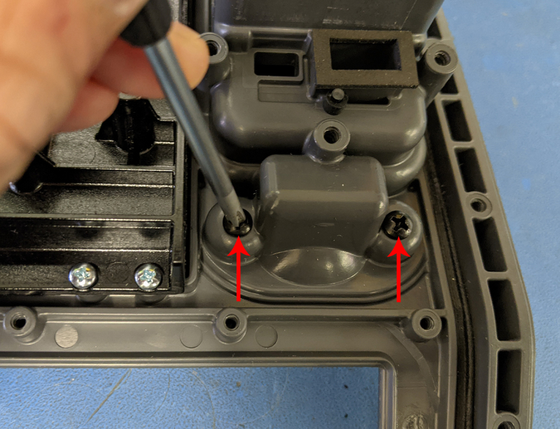
50. Put the USB cover and hinge cover in place and thread the 3 screws in place to secure it.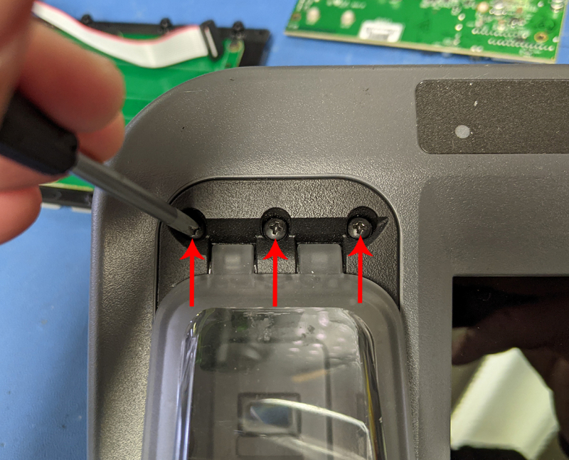
51. Put the mouse hole cover in place and secure it with 4 screws.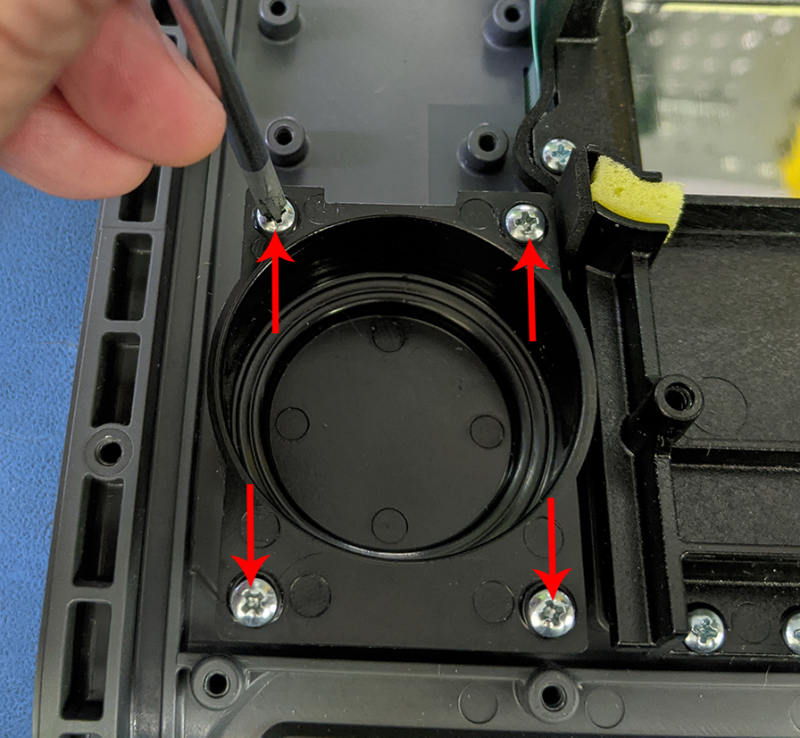
52. Plug the Wi-Fi antenna into the replacement iMX6 PCBA.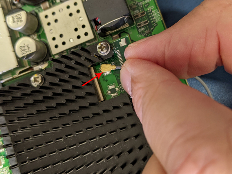
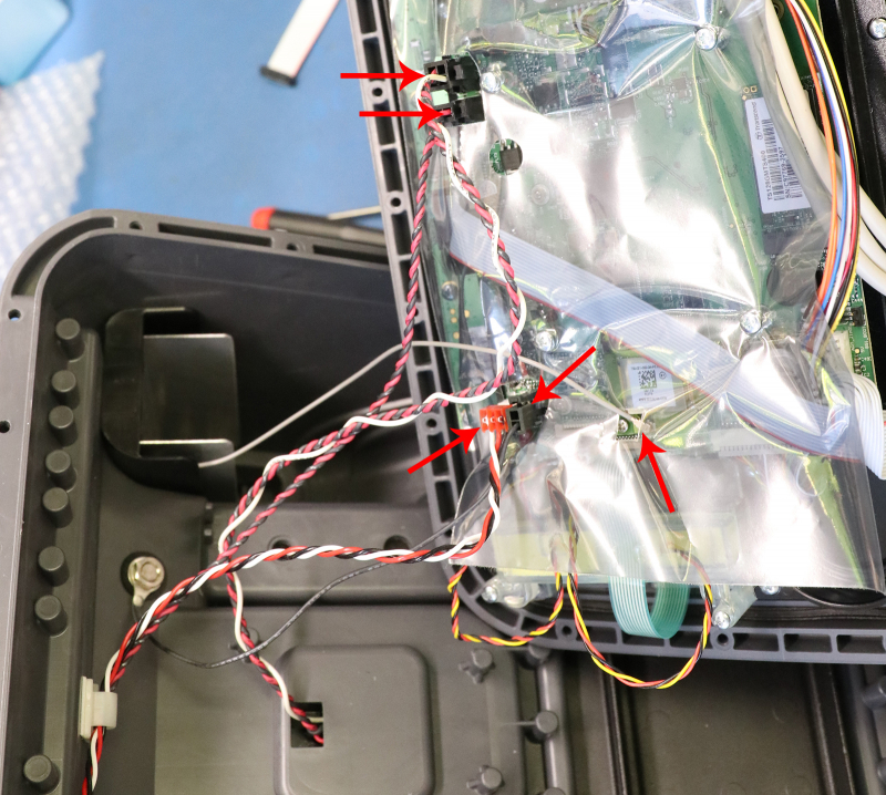
53. Place the iMX6 PCBA in place on the new LCD frame (Cable placement 1).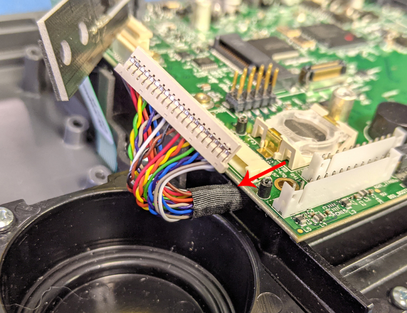
54. iMX6 PCBA Cable placement 2.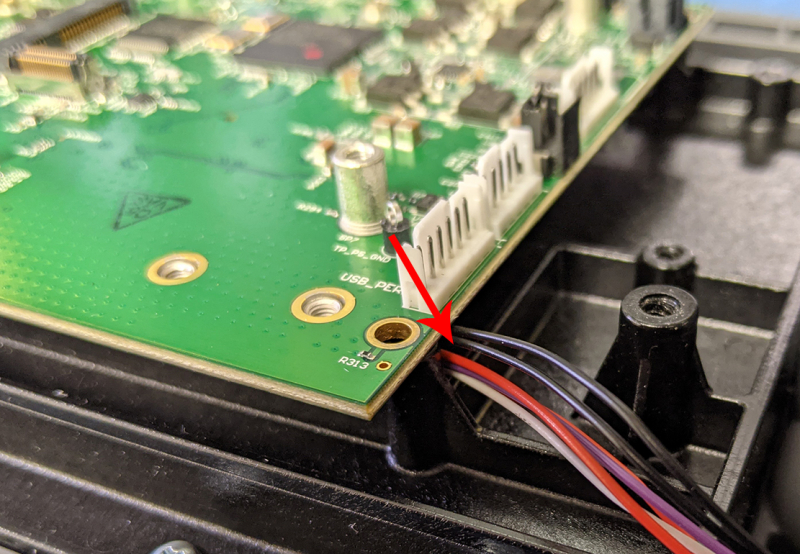
55. Secure the PCBA with 4 screws.
56. Plug the GPS module into the PCBA and secure it with the two screws.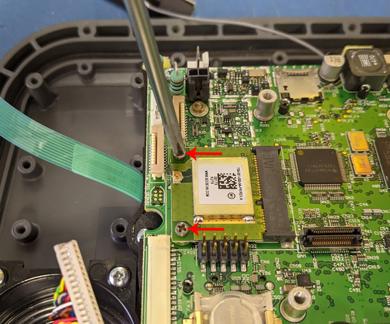
57. Plug the SSD into the PCBA and secure it with the single screw and standoff.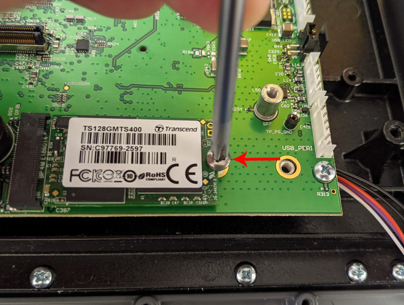
58. Install the zip tie holder and secure it by threading the single screw in place.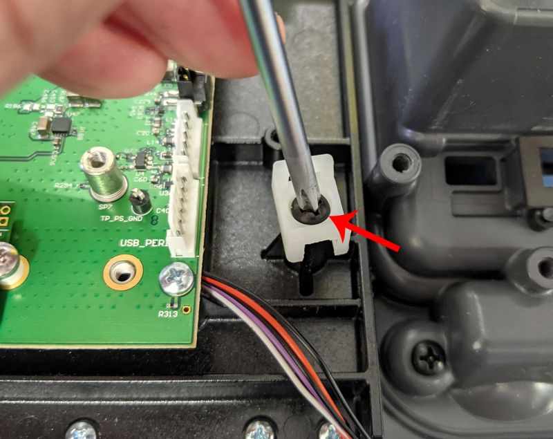
59. Install the Wi-Fi antenna holder in place thread the single screw in place to secure it.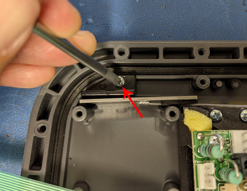
60. Plug the data cable for the LCD into the iMX6 PCBA.
61. Install the fan assembly and secure it by threading the 4 screws in place that secure it.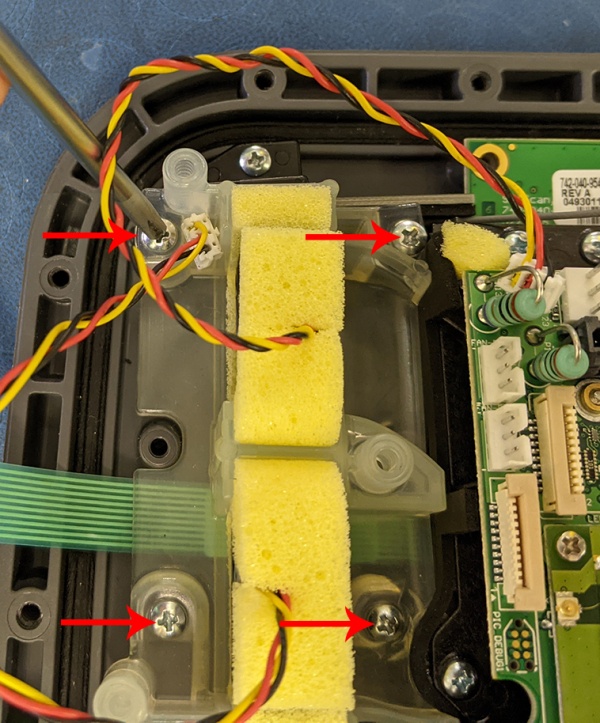
62. Install the fan assembly cover and secure it by threading the 3 screws in place that secure it.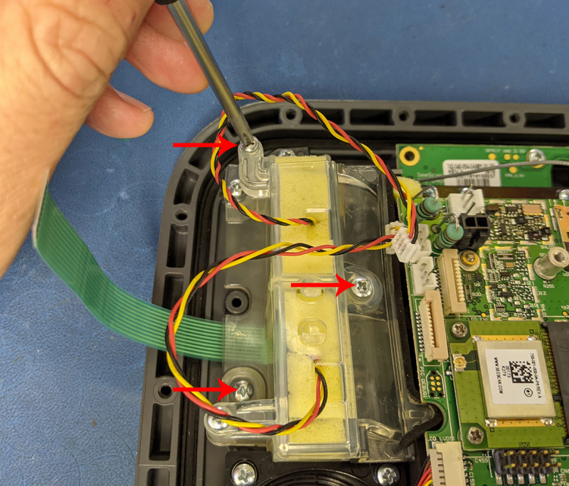
63. Plug the 2 fan cables into the connectors on the iMX6 PCBA.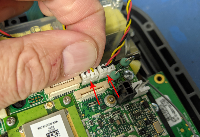
64. Thread the keypad ribbon cable through the fan assembly cover and plug it into the connector on the iMX6 PCBA.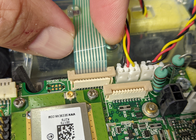
65. Set the latch for the keypad ribbon.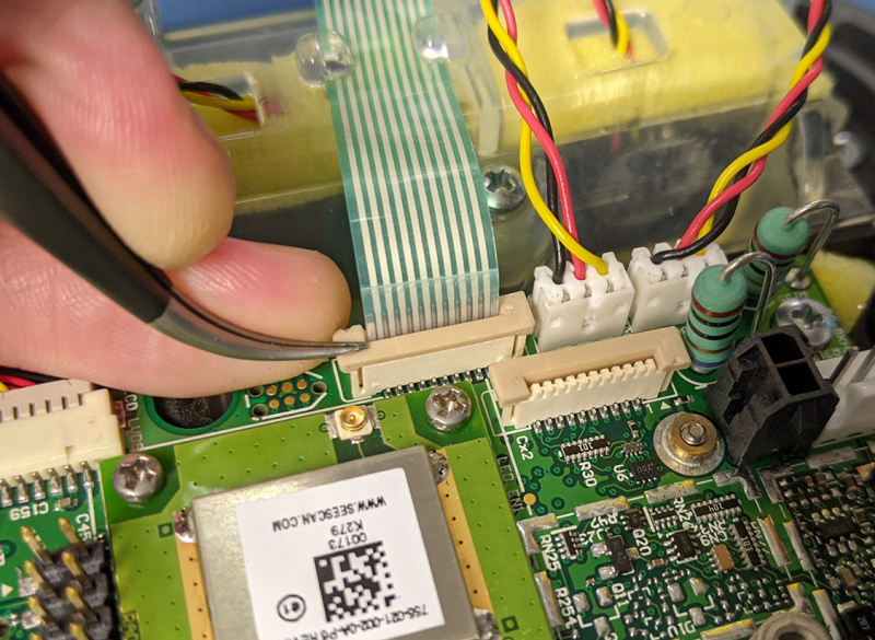
66. Put the new LCD interface board in place and secure it with the two screws that were removed from the old LCD interface board.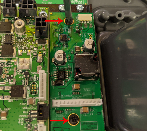
67. Plug the cable from the LCD into the interface board.
68. Route the cable through the zip tie holder.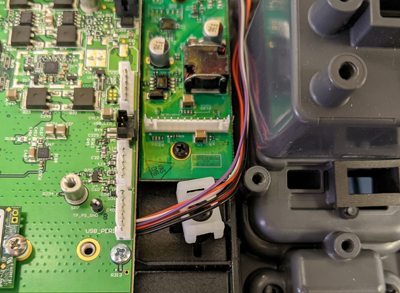
69. Plug in the new cable into the iMX6 PCBA.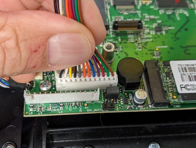
70. Plug the other end of the same cable into the interface board.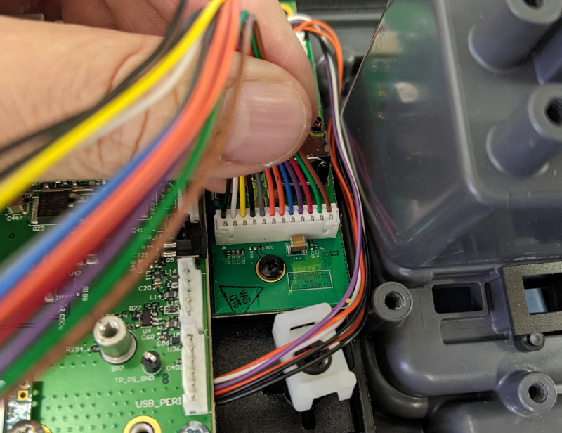
71. Place the keyboard assembly in the panel and thread the 19 screws used to secure it.
72. Place the USB boards in the appropriate spots and thread the screws in place to secure them.
- 6 for the top board
- 3 for the bottom board
73. Plug in the LED cable, the USB board cable and the USB PCBA cable into the iMX6 PCBA.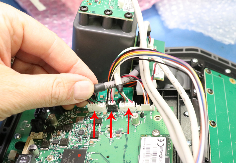
74. Secure the cables by installing a zip tie on the mount.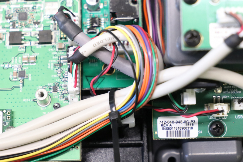
75. Plug the audio cable from the keyboard PCBA into the iMX6 PCBA.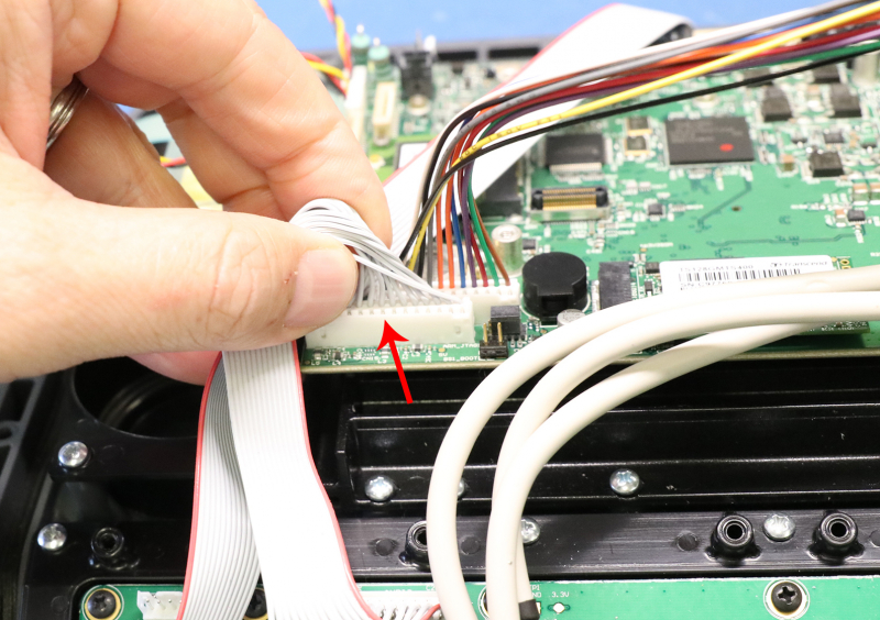
76. Install the cover on the keyboard PCBA and secure it with 6 screws.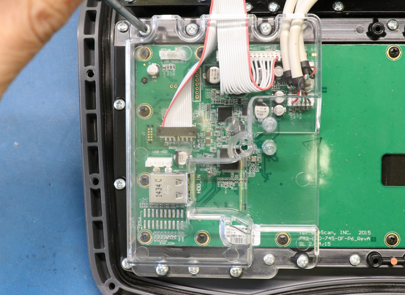
77. Install the brow board and secure it with the 2 middle screws.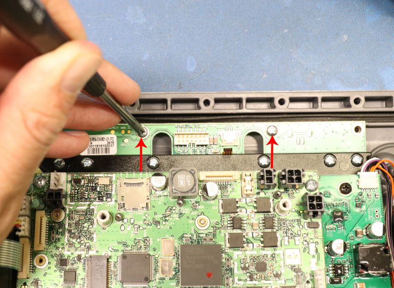
78. Install the microphone ribbon cable and set the latch.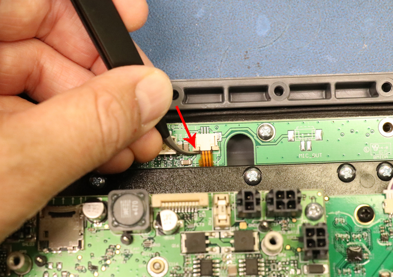
79. Plug in the brow board connector cable.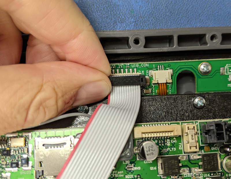
80. Place the shielding over the board and secure it with the 6 screws (2 on the brow PCBA and 4 on the iMX6 PCBA).
81. Plug the cables from the bottom case into the connectors on the iMX6 PCBA.
- Battery shoe
- External power jack
- Tracing lug
- GPS antenna
- Bulkhead connector
82. Install the front panel on the bottom case.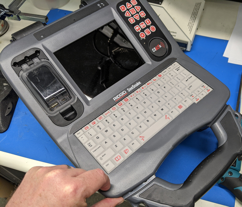
83. Hold the front panel in place, flip the unit over and thread 2 screws in place at the front.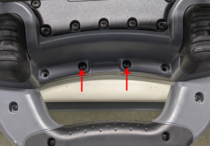
84. Thread 2 screws in place at the rear of the unit.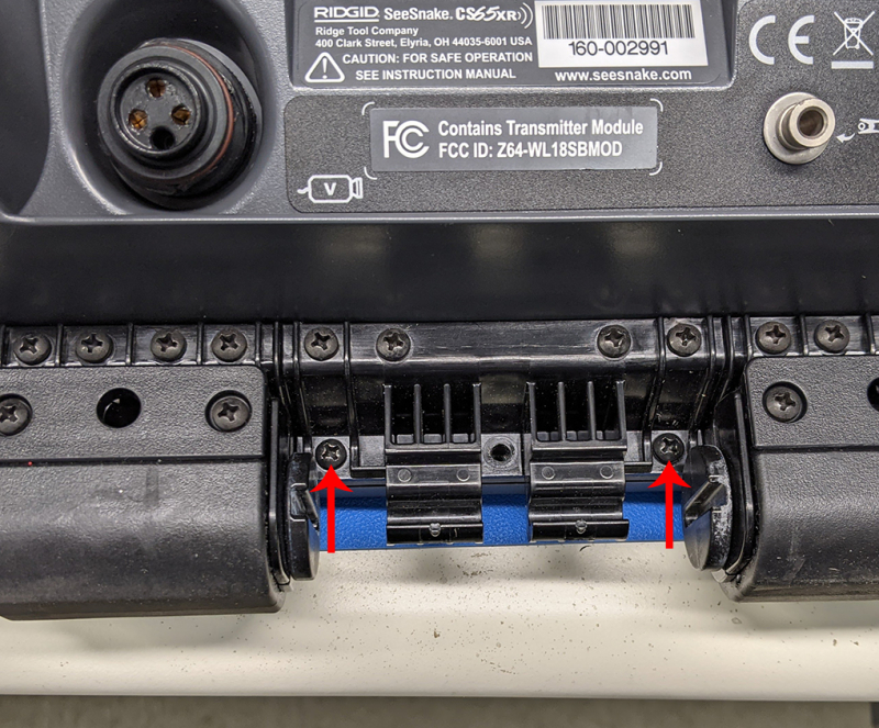
85. Install a battery and power the unit on with the power button.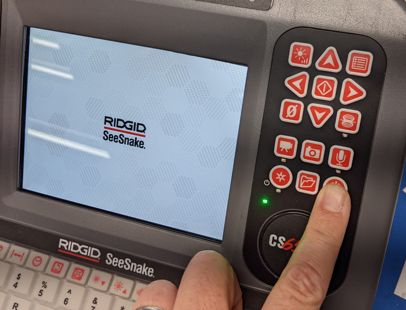
86. When prompted, use the keyboard to enter the new S/N on the included label (the text will be upside down and backwards).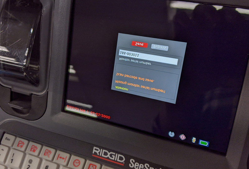
87. After the S/N is entered, and the unit reboots, it will be a fully functional CS65xr.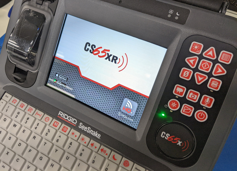
88. Heat the old S/N label with a heat gun and peel it off.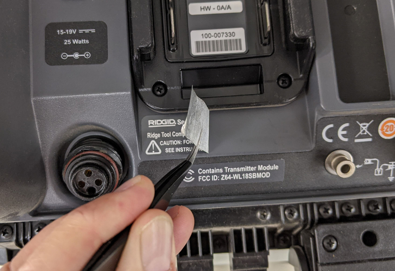
89. Install the new S/N label.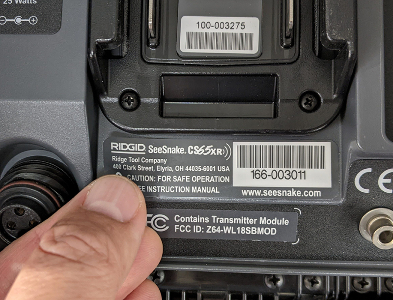
90. Thread the rest of the screws in place to secure the new front panel (front)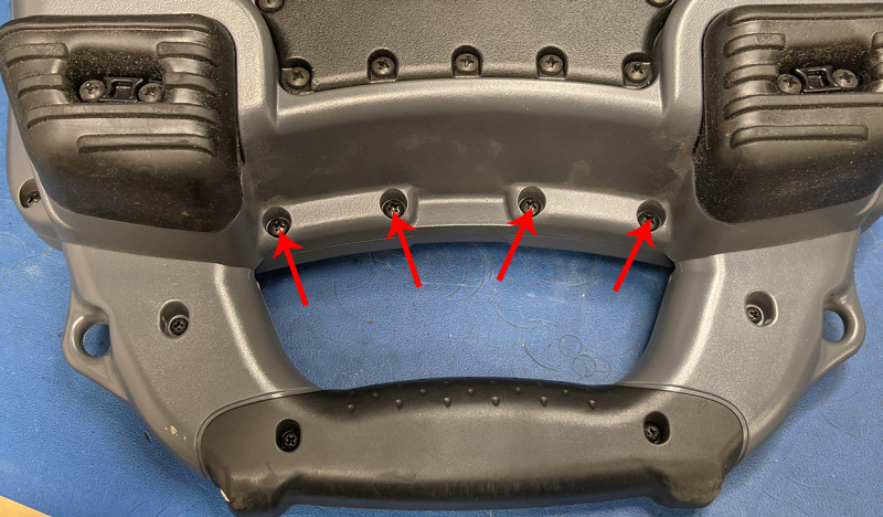
91. Side screws (same number on each side)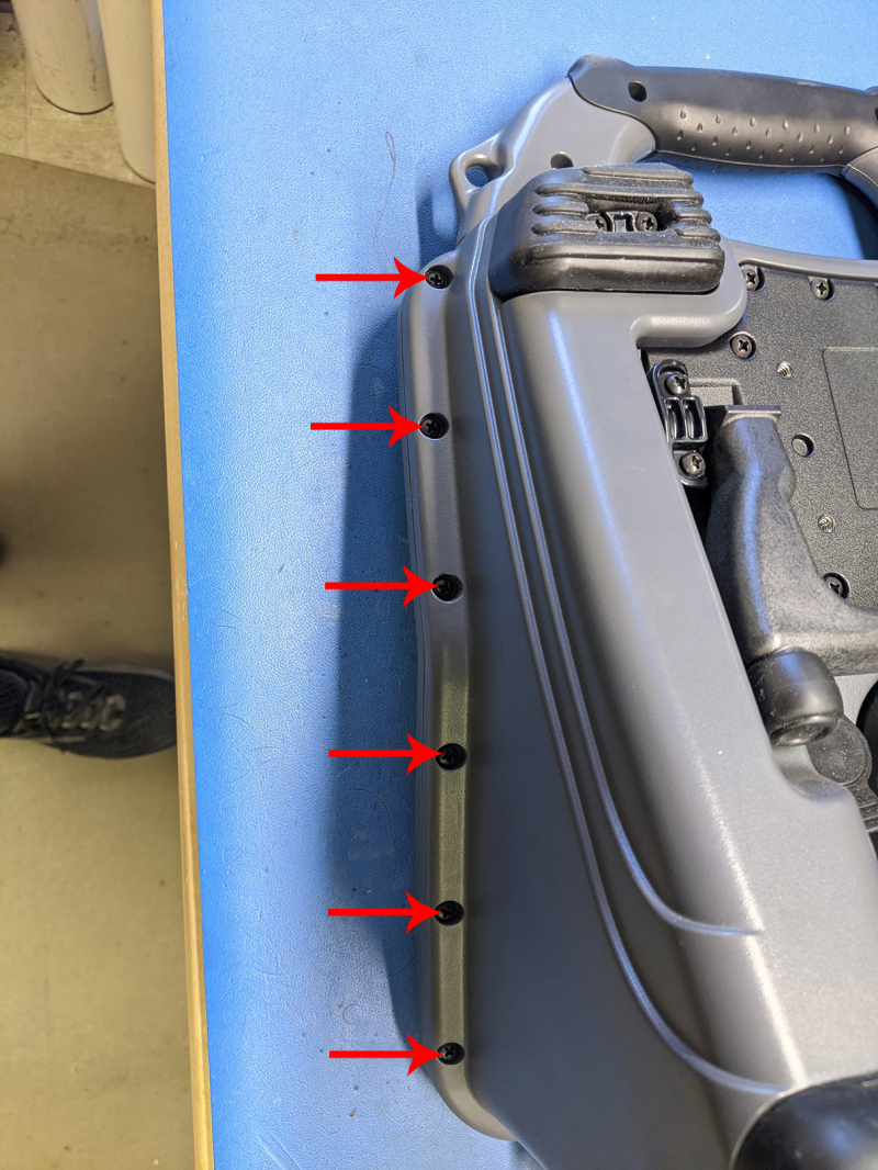
92. Back screws.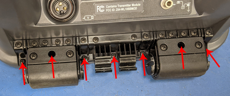
93. Re-install the top cover.